Step 1- Remove the Handle from the handle rests and place the handle in the full forward position.
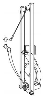
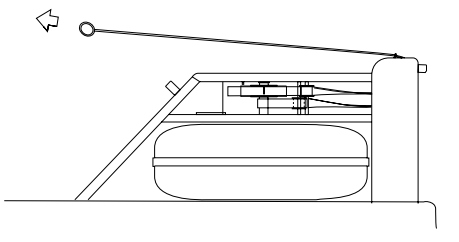
Step 2- Stand the WaterRower upright and disconnect the bungee from the Recoil Belt as shown.
Step 3- Lay the WaterRower down and slowly pull the handle so that the Drive Strap unwinds from the clutch housing. Do this gently as pulling too fast will cause the Recoil Belt to wind up too much. If you can hold the clutch.
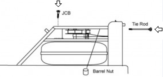
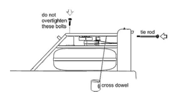
Step 4- Remove the Tie Rods and JCB Bolts connecting the Top Deck to the tank assembly as shown.
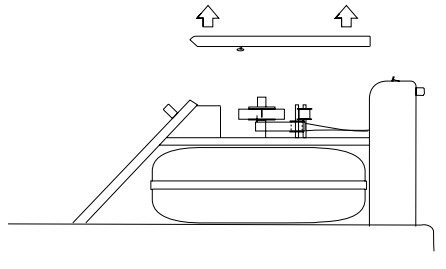
Step 5- Remove the Top Deck assembly as shown, being careful not to dislodge the guide pulleys. You may have to disconnect the Tacho pulley. Disconnect the Tacho motor plug.
Step 6- Remove the Tacho belt and the Tacho clutch pulley as shown.
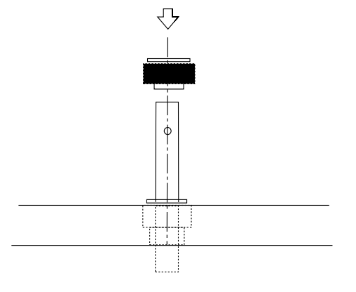
Step 7- Remove the clutch Retaining Pin as shown. You will need a hammer and punch (Slender Bolt) for this procedure.
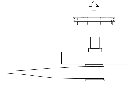
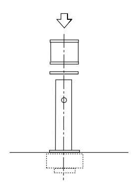
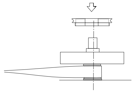
Step 8- Remove the clutch assembly as shown.
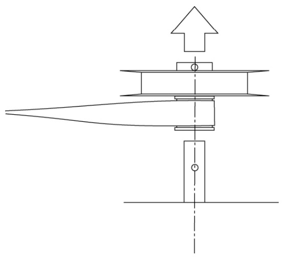
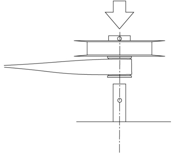
Step 9- Remove the Recoil Bush and Recoil Bush shim washer as shown.
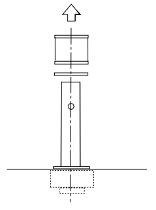
Step 10- Remove the lower paddle bush from the Bottom Deck. This may best be achieved by using a screwdriver to pry the bronze Oilite bush out of its collar and then removing the collar.
Step 11- Replace the lower paddle bush assembly into the Bottom Deck. It may be easier to first insert the rubber bush collar followed by the bronze oilite bush.
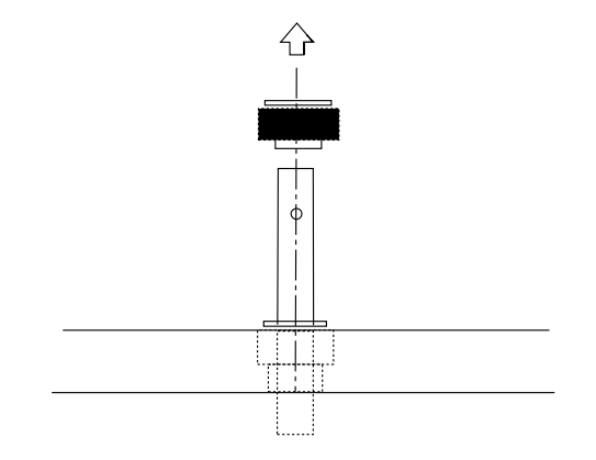
Step 12- Replace the Recoil Bush shim washer and the Recoil Bush as shown.
Step 13- Replace the clutch assembly as shown.
Step 14- Replace the clutch retaining pin as shown. It is important to make sure that the pin hole in the paddle shaft and the pin hole in the clutch line up. You may need to lift the paddle shaft to line up the 2 holes. Use a screwdriver or punch to keep these holes aligned while you hammer in the pin.
Step 15- Replace the Tacho belt and the Tacho clutch pulley as shown.
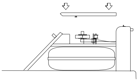
Step 16- Replace the Top Deck as shown.
Step 17- Replace the JCB bolts and Tie Rods connecting the Top Deck to the Tank assembly as shown. Ensure that the Tie Rod cross Dowel Slots are aligned with the Tie Rod. You may utilize a screw driver to assist this. Before tightening the screw, using a long slender screw driver to lift the Tacho belt onto the Tacho motor pulley and the Tacho clutch pulley.
Handle Replacement
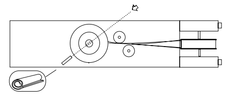
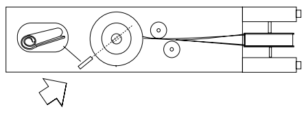
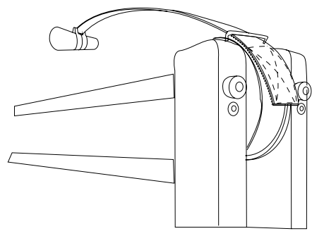
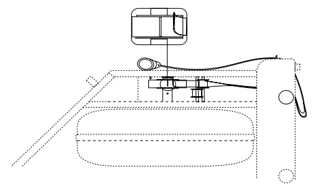
Step 18- Take the new handle assembly and pass the Velcro end over the large pulley in the Forward Riser as shown. (The Velcro should face the large pulley as it passes between the wire riser form and the pulley).
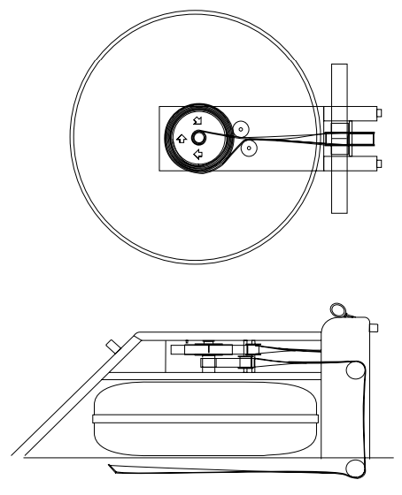
Step 19- Pass the Drive Strap around the large pulley and underneath the top Deck back towards the clutch housing. Pass the end of the Drive Strap inside (towards the center of the machine) the Drive Strap guide pulley (the upper of the two guide pulleys). Take the end of the Drive Strap and place the edge against the join in the mating Velcro on the clutch housing as shown.
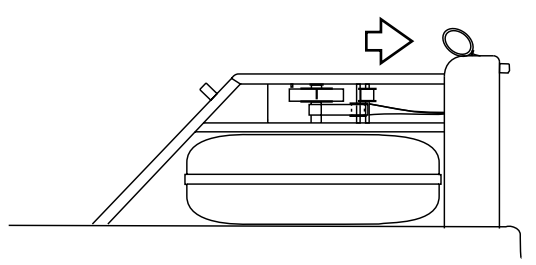
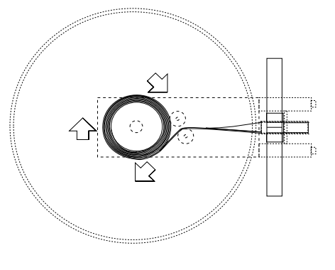
Step 20- Check that the belt orientation is correct. Slowly rotate the clutch (in a clockwise direction, as viewed from above) to feed the Drive Strap onto the clutch housing as shown. Make sure that the Drive Strap feeds evenly onto the clutch. Wind the Drive Strap onto the clutch so that the handle reaches its full forward position, as shown.
Step 21- If your Recoil Belt is still attached to the Recoil Bush then go onto step 22. Otherwise it will be necessary to reconnect the recoil. If you feel unsure about the orientation of the recoil it may be best to go through this process anyhow.
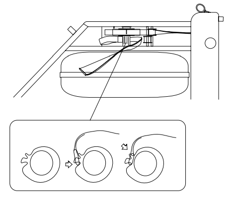
Step 22- With the handle in the full forward position, it is important that the Recoil Belt wraps around the Recoil Bush between one and two turns. Once this is so pass the Recoil Belt inside (towards the center of the machine) the Recoil Belt guide pulley (the lower of the two guide pulleys) and over the two pulleys in the Forward Riser. Pass the belt underneath the machine towards the bungee as shown.
Step 23- Stand the WaterRower upright and connect the Recoil belt to the bungee as shown.
Note: If the Recoil Belt buckle and D-Ring have been removed it will be necessary to refit them before Step 23 may be completed. Refer to the Recoil Buckle Replacement Instruction for details.