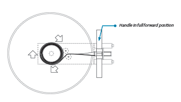
1. Remove the handle from the handle rests and place in the full forward position.
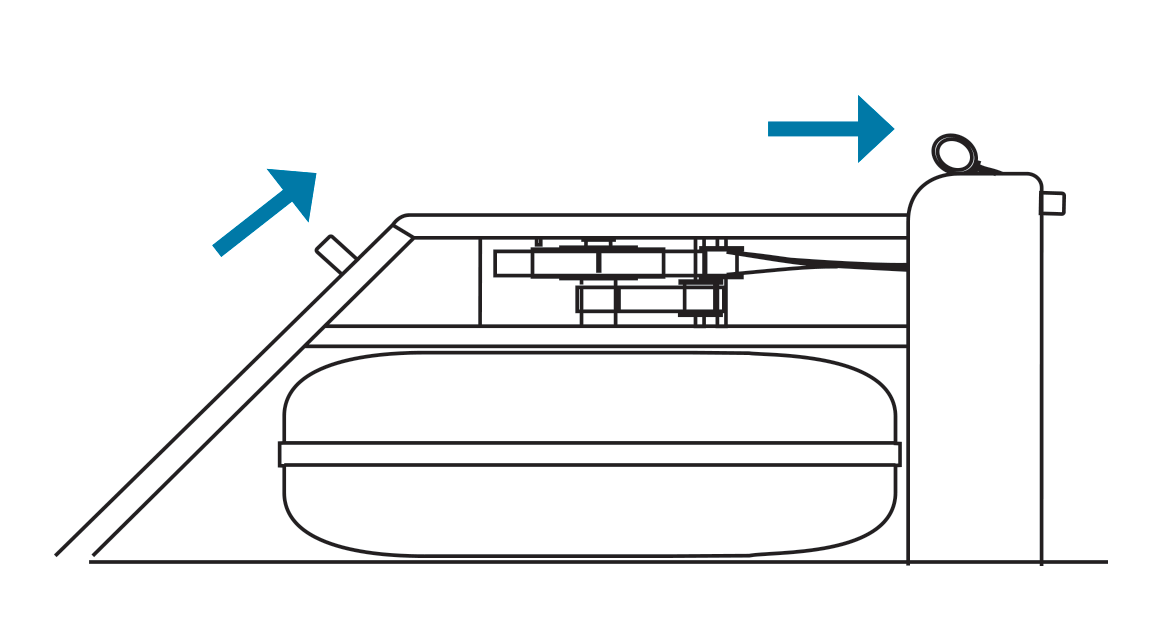
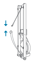
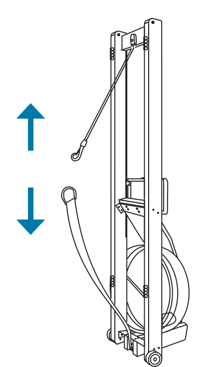
2. Stand the WaterRower upright and disconnect the bungee.
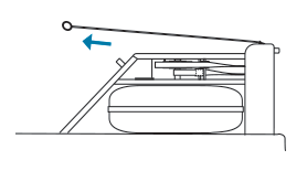
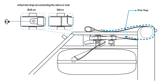
3. Lay the WaterRower down and pull the handle so the drive strap unwinds from the clutch housing. Remove the handle and drive strap from the clutch by unstrapping the velcro on the metal clutch (or removing the bolt from the plastic clutch).
*Do this slowly as pulling too fast will cause the recoil belt to wind up too much.
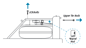
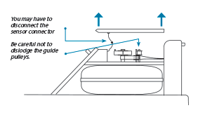
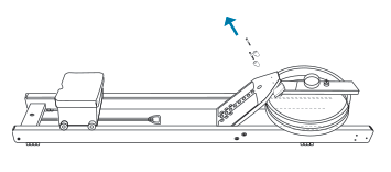
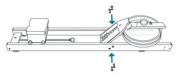
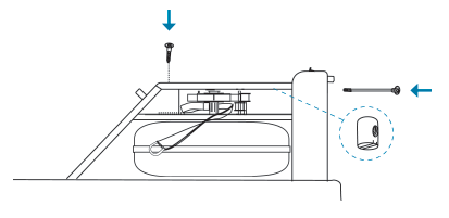
4. Remove the upper tie rods (2) and JCB bolts that connect the top deck to the assembly.
*When removing the tie rods, a barrel nut from under the top deck will come out.
Set aside for use in the new tank.
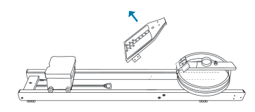
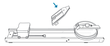
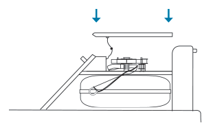
5. Gently remove the top deck assembly.
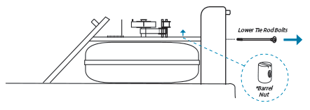
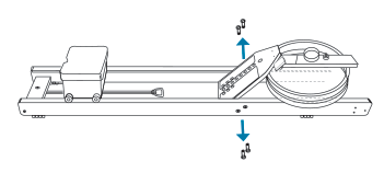
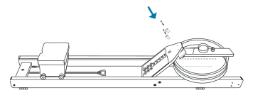
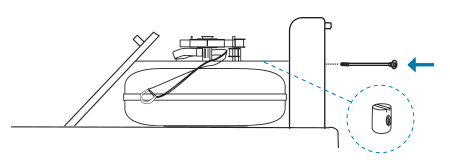
6. Remove the lower tie rod bolts (2).
**The barrel nut may need to be lifted out of the bottom deck with a flat head screwdriver. Set these aside for use in the new tank assembly.
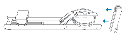
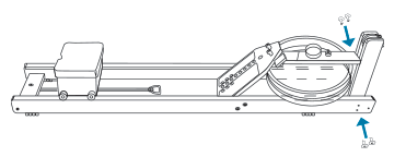
7. Remove the connecting nuts and bolts joining the forward riser bottom bracket to the rails.
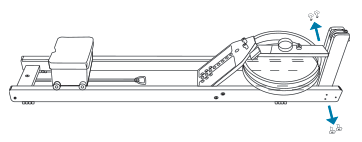
8. Remove the forward riser assembly from the tank.
9. Remove the handle rest bolts and handle rests.
10. Remove the connecting nuts and bolts joining the footboard to the rails.
11. Remove the footboard.
Refer to the diagram below for the parts that will be transferred to the new tank assembly. Transfer the
components that have the label To Be Transferred. Keep components sub-assembled as much as possible
when transferring from old tank to new tank (ie, guide pulleys & S4 monitor).

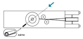
12. Remove the clutch assembly by first removing the clutch retaining roll pin.
You will need a hammer and a punch (5mm Slender Bolt) to remove the pin from the paddle shaft.
*SKIP THIS STEP IF YOUR REPLACEMENT TANK ASSEMBLY HAS A CLUTCH.
13. Remove the clutch and recoil bush assembly. Keep the recoil belt attached to the recoil bushing.
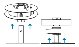
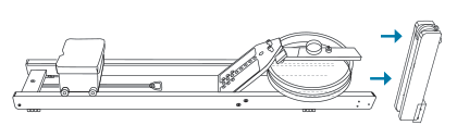
14. Remove the old tank.
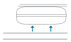
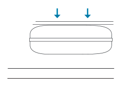
15. Place the new tank on the rails.
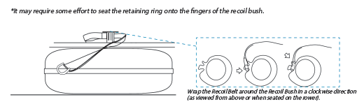
16. Replace the clutch and recoil bush assembly which includes the recoil belt. If the recoil belt is disconnected from the bushing, refer to the next step.
17. Replace the Recoil Belt (if belt is disconnected from bushing). Connect the recoil belt to the recoil bush on the paddle shaft.
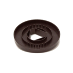
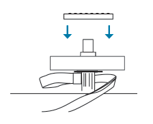
18. Replace the Sensor Disk. The sensor disk slides on the inner ring with teeth facing upwards.
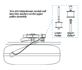
19. Replace the lower and upper guide pulleys onto the new tank.
*This may have been done in Step 4.
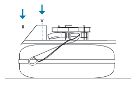
20. Replace the right and left key brackets with the bolts (4 total/2 on each side) using the 5mm Allen key.
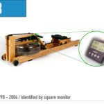
*The right key bracket will contain the monitor.
21. Replace the footboard.
22. Replace the connecting nuts and bolts joining the footboard to the rails. Keep bolts loose until all compoents are assembled and aligned.
23. Replace the handle rest bolts and handle rests. Keep bolts loose until all compoents are assembled and aligned.
24. Replace the forward riser assembly.
25. Replace the connecting nuts and bolts joining the forward riser bottom bracket to the rails. Keep bolts loose until all compoents are assembled and aligned.
26. Replace the lower tie rod bolts (2). Keep bolts loose until all compoents are assembled and aligned.
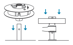
27. Replace the top deck and reconnect the sensor connector.
28. Replace the JCB bolts and upper tie rods. Ensure the tie rod opening in the barrel nuts are aligned with the tie rod. You may utilize a screwdriver to assist in replacing the barrel nut. Keep bolts loose until all compoents are assembled and aligned. Once all bolts are in alignment, go back and tighten the loose bolts from this and previous steps.
29. Ensure the handle assembly is facing the correct way and the drive strap is straight (with no twists). Pass the velcro/bolt end over the large pulley in the forward riser.
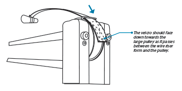
30. Pass the drive strap around the large pulley and underneath the top deck back towards the clutch housing. The end of the drive strap passes inside (towards the center of the machine) the drive strap guide pulley (the upper of the two guide pulleys).
For velcro attachment on metal clutch, take the end of the drive strap and place the edge against the side of the clutch nearest the monitor.
For plastic clutch, see image
*Clutch from above
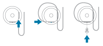
31. Once the drive straps are attached, gently pull on the recoil belt. This action re-winds the drive strap around the clutch.
By continuing to pull the recoil belt, wind the drive strap onto the clutch so the handle reaches the
full forward position.
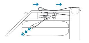
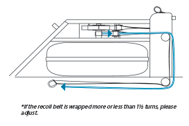
32. With the recoil belt is at its full length and wrapped 1½* turns around the recoil bushing, pass the recoil belt inside the recoil belt guide pulley and over the two pulleys in the forward riser.
33. Stand the WaterRower upright and connect the recoil belt to the bungee. Lay the WaterRower down – it is ready to use.